Crimping connection requirements for automobile terminals
-
 @
Mark Ji
- Last updated
Table of Contents
Overview requirements
Crimping connections are performed with the help of valid drawing requirements.
The special crimping dimensions (crimping height and width, etc.) of the assembly are specified in different terminal manufacturers and assembly drawings.
The pre-given crimping size is accurate.
Matched wire cross sections and terminal parts should be processed using matching crimping equipment.
Electric wire
It is not allowed to use materials that affect its electrical conductivity, such as harmful gases or oxygen aging in insulation.
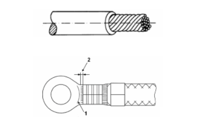
1.Wire stripping
Stripping requires the use of special tools.
The length of stripping should be monitored by special equipment.
The maximum number of copper wires will be cut by x% according to the existing wire model.
Example 1: the number of wire strands is 7 (type A wire: 0.35 mm²),5%* 7=0.36, the result is close to 0, wire strands cutting off is not allowed.
Example 2: the number of wire strands is 32 (type B wire: 1.0mm²),8%* 32=2.56, the result is close to 2, allowing a maximum of two wire strands to be cut off.
The phenomenon of copper wire breaking or damaging insulation is not allowed.
The stripped wire does not need to be dealt with immediately, and protective measures should be taken at the stripping end before breaking (e.g. insulating sleeve).
The residual material of insulation is not allowed on the surface of stripped copper wire.

Defective insulation: avoid damage to wire structure during crimping
2.Wire ends
The maximum 1mm protrusion at the end of the wire is allowed after crimping.
The protrusion of terminal of the plug, lock and screw does not affect its function.
When setting up an iron terminal, the protrusion of the wire should not reach the surface of the screw.
When a fully sealed plug terminal is used, a protrusion is not allowed.
0.4mm is allowed when only a terminal is plugged in.
The insulation between the wire and the insulation crimping area is visible.
Insulation is not allowed at the wire crimping.
Requirements of terminal crimping
1. Terminal
The terminal parts used must meet the special requirements and regulations of the part drawings, and there is no connection and unloading damage or distortion.
It needs to be coiled and erected during transportation.
When the performance of terminal parts changes, such as oxidation, it is no longer allowed to be used after aging.
2. Damage
Cross-section and grooves of terminal are not allowed to be damaged and deformed during crimping, and terminal assemblies are no longer allowed to be used when they are deformed during crimping.
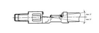
3. Bending and twisting
If there is no special description on the part drawing, the maximum longitudinal bending angle of the crimped section is not allowed to exceed 3°.

The longitudinal bending angle of the twisting crimped section is not allowed to exceed 5° (downward bending or upward bending).
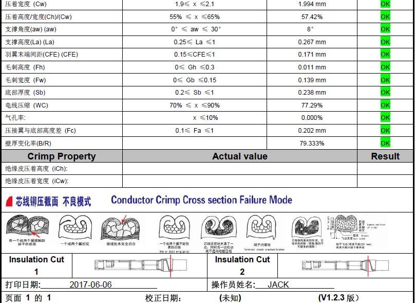
4. Wire crimping size
The thickness of the terminal material within the crimping range should be limited to the crimping size according to the part drawing.
If the actual size deviates from the standard specified in the drawing, it should also be within the range specified in the drawing.
The specified crimping dimensions shall be binding and shall be determined by the wire harness manufacturer.
Belowing is a cross-section analyzing report,


5. Appearance
- 1)Crimping length
- Conductor crimping must be closed.
- 2)Tearing
- Tearing is not allowed.
- 3)Trumpet mouth
- Trumpet mouth is required.
6. Insulation crimping
The insulation crimping of the terminal assembly matches the standard drawings of thin-walled or thick-walled wires.
Crimping angle shall be within forward 5°, backward 3°.
Crimped claws must be immersed in insulating layer.
The claw can be rolled through the insulating layer, but the wire is not allowed to be damaged.

