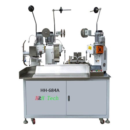
How to measure the tension of joint-wires crimping?
-
 @
Mark Ji
- Last updated
Table of Contents

Operating Videos of wire-jointly terminal crimping machines
HH-684B https://youtu.be/KFwKmfkiRMM AWG12&AWG28
HH-684B https://youtu.be/iNJLA22fv50 joint crimping+sheath/sleeve inserting
HH-684B https://youtu.be/wA5EPdZ5iIs loose terminal joint crimping
HH-684B https://youtu.be/v9OpGOt938E Conveyor belt
HH-684B https://youtu.be/xIvv8n5bhAI 4 wires joint crimping
HH-684A https://youtu.be/myhuW7gP8wA Sheath/sleeves inserting
HH-684A https://youtu.be/unAxX9R2Gx0 dual-belt terminal
HH-684A https://youtu.be/Q8VWxzNK1IA CFMs installed
HH-684A https://youtu.be/tbT3KCDTNRo Flag terminal

Crimping is the soul of wire harness processing.
The wire harness industry’s classic crimping standard USCAR21 fourth edition (2020) writes in detail the method of measuring the holding capacity of crimped connections.
The pullout force test is not used to determine the overall performance of crimping applications.
It is only used for the performance evaluation of mechanical crimping.
It will be used to determine the mechanical limits of crimping during operation.
During wire harness installation and car assembly, more protection may be needed to ensure that the connection part is not damaged.
I.Device
1. Equipment for measuring crimping height and width.
2. Open the crimping wing tool, or other suitable way to open the insulating crimping wing without damaging the conductor.
3. Force tester (tension machine).
4. sharp-nosed pliers and / or oblique pliers
II.Samples
The crimping height of each test needs at least 20 samples (at least 3 crimping heights are required, usually 5 crimping height samples are provided for better selection), and additional samples are required for wires-jointly crimping test with different wire diameters.
III.Steps
- The insulation crimping wings needs to be opened (or not crimped) when testing the drawing force.
- The drawing force test requires pre-tightening the wire (for example, to prevent incorrect jerking before the drawing force test, tighten the wire before the test).
- Record the crimping height and width of each sample with a micrometer.
- If the insulation crimping wing is not open, use suitable tools to open it to ensure that the tension only reflects the performance of the wires-jointly crimping connection.
5. Visually identify the open area of the crimping wing to ensure that wire
conductor is not damaged. Do not use if there is any damage.
6. The tension of each sample is measured and recorded in Newton.
7. The axial motion rate is at 50~250mm/min (recommended 100mm/min).
8. ①For 2-wire, 3-wire joint crimping or multi-wires, if the conductors are all below 1mm². Pull the smallest wire.
e.g.
0.35mm² wire and 0.5mm² are jointly crimped into terminal, pull the 0.35mm² wire
②For 2-wire, 3-wire joint crimping or multi-wires, if the conductors are all above 1mm². Pull the smallest wire and biggest wire.
e.g.
1)0.5mm² wire and 1.0mm² are jointly crimped into terminal, pull the both wires;
2)0.5mm² wire, 1.0mm² wire and 2.0mm² are jointly crimped into terminal, pull the 0.5mm² wire and 2.0mm² wire;
3)3×0.5mm² wires are jointly crimped into terminal, test all the three.
Note: in this case, 20 samples are required for each wire size test.
Each tension value test requires the use of a new sample.
9. Use the following formula to calculate the average and standard deviation (using EXCEL or other appropriate spreadsheet to calculate the average and standard deviation of the tension results), and the report reflects the value of minimum, maximum, average (`X), standard deviation (s) and average minus 3x standard deviation (`X-3s) of each crimping height.

Here, XI=each tension value , n = the number of samples
Formula A and B–average value and standard deviation of drawing force.
10. The report records the results of all visual inspections.
IV. Acceptance criteria
The values calculated using formulas An and B (`Xmur3s) should be consistent with or larger than the corresponding tension values in Table A and Table B.
For wires that are not listed in the table, the corresponding tension values can be calculated by using the linear interpolation of Table A and Table B.
Note: the tension value is used as a sign of crimping quality. When the pulling force of the wire is not up to the standard listed in the table due to the pulling force (which has nothing to do with crimping), it needs to be solved by engineering changes to improve the wire.
Tables A and B–pullout force requirements (mm and gauge dimensions)

Tables A

The ISO standard size is based on ISO 19642 part IV, and the SAE is based on SAE J1127 and J1128.
0.13mm2 (26 AWG) or smaller wires that require special treatment and control are not included in this standard.
For > 10mm2, the minimum value is required. You don’t need to break it completely, and you don’t need to calculate the value of (`X-3s).

